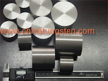
Applications which might gain more importance in the future are Construction material for the plasma chamber in magnetohydrodynamic power generation (W and W-Cu) and target plates in fusion reactors (W, W-La2O3).
Recent plasma experiments and theoretical and numerical studies show that tungsten may be the best, if not the only, material to withstand the extraordinary operating conditions in a nuclear fusion reactor divertor. The divertor, being that part of the vacuum vessel where the plasma particles interact with the first wall, and where a large fraction of the fusion heat is removed, consists of water-cooled copper heat-exchanger element covered with a plasma facing armor. The plasma particles (electrons, protons, and α-particles) are directed by the magnetic field toward the divertor target plates, where they are neutralized and pumped. The convective heat flux reaches 20 MW.m-2 and the attendant surface temperature more than 3000℃. Therefore, a suitable armor material must have a high thermal conductivity (in order to transfer high heat fluxes), low thermal expansion coefficient and low Young’s modulus (in order to keep thermal stresses low), and a high melting point and low sputtering yield (in order to keep erosion low). Although tungsten does not have as high a thermal conductivity and as low a Young’s modulus as carbon-carbon composite materials, which are foreseen for the sections of the divertor with the highest heat flux, many experts believe that, in the long run, reasonable lifetimes will only be achieved by tungsten divertor plates, which have the lowest erosion rates of all materials in sections of the divertor with relatively low plasma temperature but high particle density.
Low-pressure plasma technique
For the technical realization of low-pressure plasma processes, one requires equipment with the following components:
vacuum system (pump, vessel)
energy supply
gas supply
measurement and control components for the reproducible adjustment of the process parameter
Due to the necessity of a vacuum system in most cases, batch operation method is the easiest solution. The processes can be flexibly and complexly configured, in order to change the mode of action of the plasma through variation of the process parameters (pressure, gas flow, gas composition, power) and can attain different effects in one process step. So that, i.e. without great expenditure a secondary cleaning can be carried out and immediately thereafter a corrosion protection layer becomes deposited, without having to aerate in between.
Further advantages of low-pressure plasma technique:
ability of fissure-penetration by the plasma: even most complex sample geometries up to porous substrates can be treated
no thermal or mechanical strain of the substrates
high measure on environmental compatibility and operational safety
Chinatungsten has diverse facilities available for the various concepted questions (bulk material, batch goods, rail goods, size of the reactor up to 3m 3, MHz- and GHz stimulation); as well as many years of experience in the development of plasma processes and the conception of applicative plasma devices up to pilot graduations.
Within the bounds of its function as service provider in technology transfer, we offer its resources for the processing of the above-mentioned industrial questions up to series production. Our service comprises consultation, process development, sampling and industrial installation through pilot terotechnology.
Plasma Treatment – endless possibilities
Plasma can be used in many different cases whenever you would like to better adhere materials together or to change a surface property to suit your needs. With this trend-setting technology it is possible to modify virtually any surface. Plasma technology offers several versatile applications, for example:
Cleaning surfaces of any residues, oils, or contamination
Activation of various materials before gluing, painting, etc.
Etching and partial removal of surfaces
Coating of parts with several possible types of layers (PTFE-like, protective barriers, hydrophobic, hydrophilic, friction-reducing, etc.)
Plasma technology is establishing itself in all areas of industry, and new applications are constantly evolving.
Plasma Technology - Convincing Advantages
Compared to other methods, like flame treating or using chemicals to treat a surface, plasma technology exhibits many important advantages:
Many surface properties can be obtained exclusively with this procedure
Can be used in online production or operated independently
nvironmentally friendly process
Regardless of geometry you are able to treat powder, small parts, discs, fleece, textiles, tubing, bottles, circuit boards, etc.
Fabricated parts will not be mechanically changed
Heating of the parts is minimal
Operating costs are very low
Extremely safe to operate
Process is extremely energy efficient
Tungsten alloy is a suitable material for construction parts for plasma technique/ion propulsion. So if you have any interest in this product, please feel free to email us: sales@chinatungsten.com or call us by: 0086 592 512 9696, 0086 592 512 9595.
Felicity
Thursday, 22 April 2010


Combustion Chamber of Turbo Engines
What is Turbo Engines?
As we know, turbo engine is the heat engine which is conditioned by their maximum intake temperature, and it is limited by the behavior of the constituent materials of the articles that are most exposed to heat and constraints.
Why choose tungsten alloy?
Concerns for environmental protection have led designers of aviation turbo engines to search for means to reduce the proportion of pollutants in the exhaust gases of the engines. It is known that the principal problems in the matter of pollution of aviation turbo engines are, on the one hand, the emission of carbon monoxide, of hydrocarbons, and of various unburnt residues during operation on the ground and, on the other hand, the emission of nitrogen oxides and of particles during take-off and during cruising at altitude. There fore, tungsten alloy products are increasingly accepted by public in this case.
Conventional combustion chambers are generally of optimized rating for take-off or near take-off operation. This signifies that, in the primary zone of the combustion chamber, a fraction of the air flow of the compressor is introduced so that, with the injected fuel, the fuel-air mixture in this zone would be essentially stoichiometric in these modes. Under these conditions, due to the levels of temperature and high pressures, as complete as possible a combustion is obtained, combustion yields greater than 0.99 are attained, the speeds of the chemical reaction being optimum for these stoichimoetric mixtures.
In contrast, at low ratings, at idle or nearly so, the total richness in the chamber is only about half that at take-off; in addition, the pressures and temperatures at the outlet of the compressor are lower; the result is that the chamber, with the partial charge is very much maladjusted and that the slow speed combustion efficiency rarely goes beyond 0.93. The combustion is, therefore, very incomplete, which means much higher concentrations of carbon monoxide and unburnt residues at the exhaust than under normal operation. The proportions of the pollutants are all the higher, the lower the total yield of the combustion.
However, it appears to be possible to improve the performance of a combustion chamber by acting on four factors:
The timing of vaporization of the fuel,
The timing of the air-fuel mixture,
The timing of the fresh gas/burnt gas mixture,
The timing of the chemical reaction.
The first two times can be considered negligible at high ratings because of the pressures which are attained, but it is not so at low ratings. In fact, in order to increase the speed of the vaporization of the fuel, it must be transformed into fine droplets, which, in normal operation, is easily realized by the conventional mechanical atomizing injector, but the performance which is obtained in the lower ratings is poor. This is due to the fact that, if the fuel is well divided into droplets, these are poorly mixed with air in the primary zone and local zones would appear which have a richness which is too high. In the end, it would be necessary that each droplet would have around it the quantity of gas necessary for its vaporization and for its combustion, i.e., a quantity of gas which results in a stoichiometric mixture with the oxygen molecules after complete varporization. In order to accomplish this, systems such as aerodynamic injection have been proposed. Aerodynamic type injectors generally comprise whirling, or swirler vanes through which the air from the compressor is introduced, which serves to atomize the fuel. An air/fuel pre-mixture is thus obtained.
The fresh gas/burnt gas mixture must also be advantageous because it contributes to the increase in the temperature of the carburized mixture and, therefore, aids in its atomization and consequently permits an improvement in the speed of the chemical reaction. In conventionally allowing this contact of the carburized mixture with the high temperature gas from the combustion it is desirable to arrange for a recirculation of the latter by searching for a convenient turbulence level.
All of these solutions, which allow an improvement in the combustion yield have, however, a maximum efficiency only for values sufficient for the pressures and temperatures of the air at the chamber inlet.
As far as the reaction time is concerned, it is necessary to additionally research an optimization of the richness of the mixture, the ideal would be to be able to obtain a stoichiometric air/fuel proportion in the flame stabilization zone, regardless of the operation of the engine.
A first objective of this product is to provide a novel solution to the problem of low operating combustion for a chamber which includes aerodynamic type or pre-atomization injectors, which are mounted in the base of the chamber. In fact, in the case of a conventional chamber of this type, which is arranged to provide a stoichiometric mixture at take-off, about one-third of the air flow necessary for the combustion is introduced in the injection system and two-thirds by the primary orifices.
All of these factors are advantageous for a reduction of the reaction times and could lead to a reduction of the length of the combustion chamber and thus to a limitation of the dwell time of the gases in the latter.
As far as the chambers of the annular or nozzle-shaped type are concerned, it is possible to design the intermediate segment in the form of an annular zone which is common to all the injectors. The intermediate segment would then be formed of a circular base located in a plane which is perpendicular to the axis of the chamber to which the injectors are attached, and of two annular lateral walls which are welded, at the one end, to the circular base and on the other end to the base of the chamber, defining an annular volume which flares towards downstream, various forms could be adapted for the lateral walls, in a manner analogous to the case of the intermediate segment itself to each injector. They could each particularly be generated by a straight line and then each form a conic wall at the downstream end on which the holes, which are designed for the introduction of the fourth flow of air are located, distributed over one or several circles which are located on one or several planes which are perpendicular to the axis of the chamber. Each of the lateral walls could be formed of two truncated conical sections, with the connecting axes welded end to end, of which the angles at the top increase towards downstream, the small diameter holes which are designed for the injection of the fourth air flow being located immediately ahead of the joint which is formed by the joining of the two truncated cones, and distributed over one or several planes which are perpendicular to the common axis of the truncated cones. They could also be formed of a first truncated portion, with a top angle between 60° and 100°, comprising, at its downstream end, an annular zone which is located in a plane which is perpendicular to the axis of the chamber, in which the small diameter holes are drilled, which are designed for the injection of the fourth air flow, the holes being distributed over one or several circles which are coaxial with the said zone and having their axis normal to the generators of the truncated portion, to which an annular zone is joined where they are drilled. This last arrangement proves to be particularly advantageous in the case of a high performance chamber because of the fact that it suppresses the hot slip-streams behind the jets which correspond to the fourth flow.
The diameter of the holes, which are designed for the injection of the fourth flow, in the intermediate annular segment, which will represent 1/6 to 1/3 of the primary air, will have a diameter between 1/10 and 1/40 of the maximum dimension of the flared segment, measured on a radius of the chamber.
The cooling of the downstream ends of each lateral wall by a fifth air flow obviously works, the holes which are designed for the injection of this fifth flow being located in the immediate proximity of the joint between each lateral wall and the chamber, the values of the angles and the flow being identical to that mentioned in the case of the chambers for which each injector possesses its own intermediate segment.
The penetration of the intermediate segment could also be realized in order to increase the volume of the secondary recirculation zone; its depth of penetration will then be between one-fifth and one-half of the maximum dimensions of the intermediate segment, measured on a radius of the chamber.
Chinatungsten can offer tungsten alloy products used in this case not only according to international standard, but also as per customer’s requirements. Tungsten alloy is a suitable material for combustion chamber of turbo engines. So if you have any interest in this product, please feel free to email us: sales@chinatungsten.com or call us by: 0086 592 512 9696, 0086 592 512 9595. We are at your service.
Felicity
As we know, turbo engine is the heat engine which is conditioned by their maximum intake temperature, and it is limited by the behavior of the constituent materials of the articles that are most exposed to heat and constraints.
Why choose tungsten alloy?
Concerns for environmental protection have led designers of aviation turbo engines to search for means to reduce the proportion of pollutants in the exhaust gases of the engines. It is known that the principal problems in the matter of pollution of aviation turbo engines are, on the one hand, the emission of carbon monoxide, of hydrocarbons, and of various unburnt residues during operation on the ground and, on the other hand, the emission of nitrogen oxides and of particles during take-off and during cruising at altitude. There fore, tungsten alloy products are increasingly accepted by public in this case.
Conventional combustion chambers are generally of optimized rating for take-off or near take-off operation. This signifies that, in the primary zone of the combustion chamber, a fraction of the air flow of the compressor is introduced so that, with the injected fuel, the fuel-air mixture in this zone would be essentially stoichiometric in these modes. Under these conditions, due to the levels of temperature and high pressures, as complete as possible a combustion is obtained, combustion yields greater than 0.99 are attained, the speeds of the chemical reaction being optimum for these stoichimoetric mixtures.
In contrast, at low ratings, at idle or nearly so, the total richness in the chamber is only about half that at take-off; in addition, the pressures and temperatures at the outlet of the compressor are lower; the result is that the chamber, with the partial charge is very much maladjusted and that the slow speed combustion efficiency rarely goes beyond 0.93. The combustion is, therefore, very incomplete, which means much higher concentrations of carbon monoxide and unburnt residues at the exhaust than under normal operation. The proportions of the pollutants are all the higher, the lower the total yield of the combustion.
However, it appears to be possible to improve the performance of a combustion chamber by acting on four factors:
The timing of vaporization of the fuel,
The timing of the air-fuel mixture,
The timing of the fresh gas/burnt gas mixture,
The timing of the chemical reaction.
The first two times can be considered negligible at high ratings because of the pressures which are attained, but it is not so at low ratings. In fact, in order to increase the speed of the vaporization of the fuel, it must be transformed into fine droplets, which, in normal operation, is easily realized by the conventional mechanical atomizing injector, but the performance which is obtained in the lower ratings is poor. This is due to the fact that, if the fuel is well divided into droplets, these are poorly mixed with air in the primary zone and local zones would appear which have a richness which is too high. In the end, it would be necessary that each droplet would have around it the quantity of gas necessary for its vaporization and for its combustion, i.e., a quantity of gas which results in a stoichiometric mixture with the oxygen molecules after complete varporization. In order to accomplish this, systems such as aerodynamic injection have been proposed. Aerodynamic type injectors generally comprise whirling, or swirler vanes through which the air from the compressor is introduced, which serves to atomize the fuel. An air/fuel pre-mixture is thus obtained.
The fresh gas/burnt gas mixture must also be advantageous because it contributes to the increase in the temperature of the carburized mixture and, therefore, aids in its atomization and consequently permits an improvement in the speed of the chemical reaction. In conventionally allowing this contact of the carburized mixture with the high temperature gas from the combustion it is desirable to arrange for a recirculation of the latter by searching for a convenient turbulence level.
All of these solutions, which allow an improvement in the combustion yield have, however, a maximum efficiency only for values sufficient for the pressures and temperatures of the air at the chamber inlet.
As far as the reaction time is concerned, it is necessary to additionally research an optimization of the richness of the mixture, the ideal would be to be able to obtain a stoichiometric air/fuel proportion in the flame stabilization zone, regardless of the operation of the engine.
A first objective of this product is to provide a novel solution to the problem of low operating combustion for a chamber which includes aerodynamic type or pre-atomization injectors, which are mounted in the base of the chamber. In fact, in the case of a conventional chamber of this type, which is arranged to provide a stoichiometric mixture at take-off, about one-third of the air flow necessary for the combustion is introduced in the injection system and two-thirds by the primary orifices.
All of these factors are advantageous for a reduction of the reaction times and could lead to a reduction of the length of the combustion chamber and thus to a limitation of the dwell time of the gases in the latter.
As far as the chambers of the annular or nozzle-shaped type are concerned, it is possible to design the intermediate segment in the form of an annular zone which is common to all the injectors. The intermediate segment would then be formed of a circular base located in a plane which is perpendicular to the axis of the chamber to which the injectors are attached, and of two annular lateral walls which are welded, at the one end, to the circular base and on the other end to the base of the chamber, defining an annular volume which flares towards downstream, various forms could be adapted for the lateral walls, in a manner analogous to the case of the intermediate segment itself to each injector. They could each particularly be generated by a straight line and then each form a conic wall at the downstream end on which the holes, which are designed for the introduction of the fourth flow of air are located, distributed over one or several circles which are located on one or several planes which are perpendicular to the axis of the chamber. Each of the lateral walls could be formed of two truncated conical sections, with the connecting axes welded end to end, of which the angles at the top increase towards downstream, the small diameter holes which are designed for the injection of the fourth air flow being located immediately ahead of the joint which is formed by the joining of the two truncated cones, and distributed over one or several planes which are perpendicular to the common axis of the truncated cones. They could also be formed of a first truncated portion, with a top angle between 60° and 100°, comprising, at its downstream end, an annular zone which is located in a plane which is perpendicular to the axis of the chamber, in which the small diameter holes are drilled, which are designed for the injection of the fourth air flow, the holes being distributed over one or several circles which are coaxial with the said zone and having their axis normal to the generators of the truncated portion, to which an annular zone is joined where they are drilled. This last arrangement proves to be particularly advantageous in the case of a high performance chamber because of the fact that it suppresses the hot slip-streams behind the jets which correspond to the fourth flow.
The diameter of the holes, which are designed for the injection of the fourth flow, in the intermediate annular segment, which will represent 1/6 to 1/3 of the primary air, will have a diameter between 1/10 and 1/40 of the maximum dimension of the flared segment, measured on a radius of the chamber.
The cooling of the downstream ends of each lateral wall by a fifth air flow obviously works, the holes which are designed for the injection of this fifth flow being located in the immediate proximity of the joint between each lateral wall and the chamber, the values of the angles and the flow being identical to that mentioned in the case of the chambers for which each injector possesses its own intermediate segment.
The penetration of the intermediate segment could also be realized in order to increase the volume of the secondary recirculation zone; its depth of penetration will then be between one-fifth and one-half of the maximum dimensions of the intermediate segment, measured on a radius of the chamber.
Chinatungsten can offer tungsten alloy products used in this case not only according to international standard, but also as per customer’s requirements. Tungsten alloy is a suitable material for combustion chamber of turbo engines. So if you have any interest in this product, please feel free to email us: sales@chinatungsten.com or call us by: 0086 592 512 9696, 0086 592 512 9595. We are at your service.
Felicity
Actuator in Self-winding Watches

What is actuator in self-winding watches?
An automatic or self-winding watch is a mechanical watch, whose mainspring is wound automatically by the natural motion of the wearer's arm, to make it unnecessary to manually wind the watch. Most mechanical watches sold today are self-winding.
(you can see more details in http://en.wikipedia.org/wiki/Automatic_watch)
How it works?
The mechanism of most automatic watch movement is based on the hand-winding mechanical watch movement.
To become automatic, the watch contains a semicircular 'rotor', an eccentric weight that turns on a pivot, within the watch case. The normal movements of the user's arm and wrist cause the rotor to pivot back-and-forth on its staff, which is attached to a ratcheted winding mechanism. The motion of the wearer's arm is thereby translated into the circular motion of the rotor that, through a series of reverser and reducing gears, eventually winds the mainspring. Modern self-winding mechanisms have two ratchets and wind the mainspring during both clockwise and counterclockwise rotor motions.
The fully-wound mainspring in a typical watch can store enough energy reserve for roughly two days, allowing automatics to keep running through the night while off the wrist. Usually automatic watches can also be wound manually by turning the crown, so the watch can be kept running when not worn, and in case the wearer's wrist motions are not sufficient to keep it wound automatically.
In it, tungsten alloy is a very important component. So if you have any interest in this product, please feel free to email us: sales@chinatungsten.com or call us by: 0086 592 512 9696, 0086 592 512 9595.
Felicity
Monday, 19 April 2010
Syringe Shield


Syringe Shield 3cc:
Introduction:
9 mm thick glass-5.2g/cc gives optimum protection and is easily replaced. Fully exposed needle hub allows you to visually check for correct venous insertion prior to injection.
Weight: Without glass:
2.5cc: 0.3 lbs (0.14kg)
3cc: 0.36 lbs (0.16kg)
5cc: 0.4 2bs (0.19kg)
10cc: 0.62 lbs (0.28kg)
With glass:
3cc: 0.42 lbs (0.19kg)
5cc: 0.53 lbs (0.24kg)
10cc: 0.77 lbs (0.35kg)
Drawing Syringe Shield 3cc
Introduction:
2 mm solid tungsten flange helps shield the hand when withdrawing liquid from a vial. Flange is easily removed to allow transition from drawing dose to patient injection. 9 mm thick glass-5.2g/cc gives the greatest protection of any glass in any syringe shield and is easily replaced. twist-turn and the syringe is held firmly.
Material: tungsten
Weight:
3cc: 0.77 lbs (0.35kg)
5cc: 1.06 lbs (0.48kg)
10cc: 1.5 lbs (0.68kg)
PETPig Syringe Pig/Syringe Shield
PETPig permits the safe transport and administration of unit dose PET radiopharmaceuticals. The “T”handle on the PETPig cap allows the unit to be easily lifted out of traditional “ammo can” delivery cases. The use of the thermos style handle reduces hand exposure by permitting the PETPig to be carried to the imaging suite without holding container sidewalls. Prior to injection, the base unscrews, allowing the center portion to be used as a syringe shield. When placed in the optional PETPig Cradle, patient administrations can be performed with ease and maximum shielding.
Weight: 15.6 lbs
PET Dispensing System Syringe Shield 3/5 cc
The PET Syringe Shield magnetically docks with the PET Dispensing Pig .Designed to accept 3cc and 5cc B-D syringes ,it places the needle inside the vial septum when engaged . The external calibration rod allows the precise volume to be withdrawn without a leaded glass viewing port ,where high exposure levels cannot be adequately shielded .
Sunday, 18 April 2010
X-ray target & collimator
X-ray Target
X-ray target can be subjected to higher loadings than stationary anodes. By rotation of dish-shaped X-ray targets under the electron beam, a new, already cooled part of the target surface is continually used as the focal spot. Moreover, the X-ray target cools down more rapidly by radiating its heat. Far more energy per unit time can therefore be supplied to an X-ray tube with an X-ray target in comparison with a stationary anode.
Multi leaf collimator
Radiotherapy destroys cancer by directing beams of radiation directly onto the tumor. The beams of radiation require a very fine focus to avoid harming the surrounding healthy tissue. This focus is achieved by using a multi-leaf collimator, consisting of two rows of very thin tungsten alloy plates, which can be configured to exactly match the dimensions of the tumor.
Collimators and shielding made of tungsten heavy alloy groundbreaking components in the medical industry. They contribute significantly to successful radiotherapy through their high density and high shielding capability against X-rays and gamma rays.
Tungsten Alloy Counterbalance /Counterweight
Tungsten Alloy Counterbalance /Counterweight
Tungsten alloy Counterbalance weight is used in applications such as yacht, sailboat, submarine and other vessels crank camshafts, holders for Well Logging, Racing Weights. vibration damping and dynamic balancing.
The high density and metallurgical properties found in tungsten heavy alloys make it an excellent casing material for down hole logging of oil wells. ATI Firth Sterling has years of experience in producing high properties in large bars of class 1, 2, or 3 material. ATI Firth Sterling can supply Densalloy™ in pressed & sintered blanks large enough to yield the desired component or machined components to customer’s specifications.
Geologging
Geologging is an exploration technique used mainly in the oil and gas industries. It is also known as wireline logging and borehole logging. A gamma ray source is lowered into a borehole and the radiation penetrates the rock strata. This data can then be analysed to determine whether deposits of gas or oil are present. tungsten alloy is used to shield the radioactive source and to act as a collimator for the gamma beam.
  |  |
 | |
 |  |
Balls: φ 2mm above
Shafts: (φ2mm above)×(Length max.600mm)
Sheets: (Thickness 0.15mm above) ×(Wideness max.200mm)×(Length max.500mm)
Square, round and rectangle sizes: diameter 550mm above
According the demanding
Tungsten Heavy Alloy (WHA) in Aerospace
Tungsten Heavy Alloy (WHA) in Aerospace
Tungsten alloys are generally used by aerospace designers for balancing components or reducing vibration. The high density of tungsten materials allows maximum sensitivity from optimum mass and is particularly valuable in situations where a large mass has to be contained in a confined space.
Examples of applications
| Trim Weights Anti-Flutter Weights Flight control surfaces
Anti-Vibration Weights
Rotor Blades
Propeller Blades
Inertial Systems
Ballast Weights
Dimensions: | |


Subscribe to:
Posts (Atom)